Detector
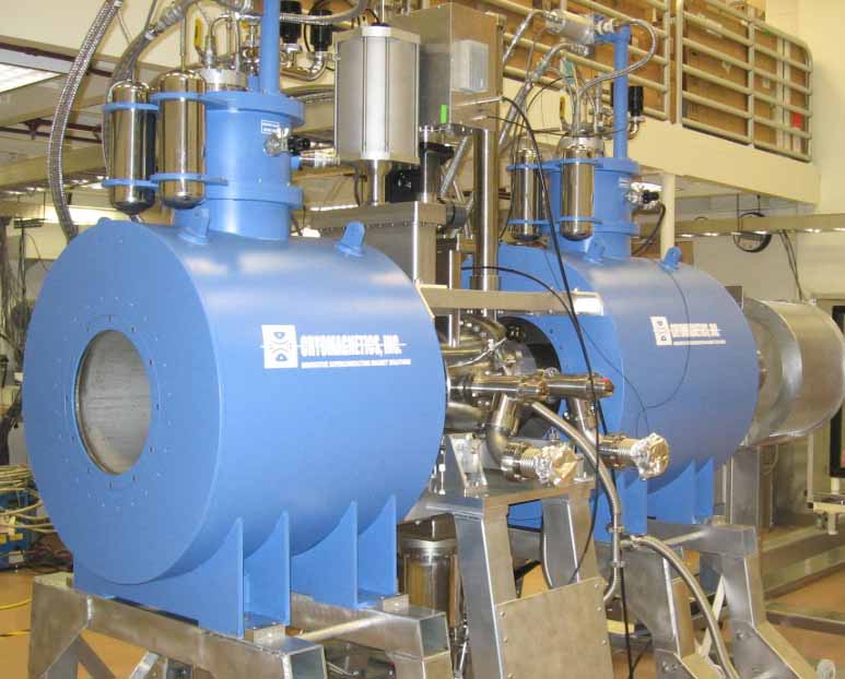
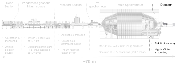
After passing the retarding potential of the main spectrometer all β-electrons are re-accelerated to their initial energy and magnetically guided to the focal plane detector (FPD). The FPD is located inside the second magnet of a pair of superconducting magnets. To lower the detector background rate, the large diameter, warm bore, of this solenoid magnet is wide enough to accommodate active and passive detector shielding. The detector is a multi-pixel silicon semiconductor detector with high energy resolution and thin entrance window.
In principle KATRIN would only require a simple electron counter to determine how many electrons have crossed the retarding potential. In practice, energy, spatial, and temporal information is very important in both understanding the operation of the apparatus and sources of background. The two main reasons we need more information than just counting of the electrons are:
- The electric potentials e.g. at the source and at the analyzing plane of the main spectrometer vary slightly, depending on the radial position. These distortions can be calculated or measured. The position of the electrons as it passes the analyzing plane is imaged in the position at which it strikes the detector. A position-sensitive detector allows the varying electric potentials to be mapped and to apply corrections to each detected electron.
- There are various sources of background, mainly electrons produced by ionization in the residual gas, electrons from interactions of cosmic rays, and γ-rays from natural radioactivity emanating from material surrounding the detector and from the detector itself. Here, positional information also helps, but most important is the accurate determination of the electron's energy. β-electrons of interest occur in a narrow energy window, whereas backgrounds vary over a large range of energies, thus, accurate energy determination improves the ability to separate β-electrons for backgrounds.
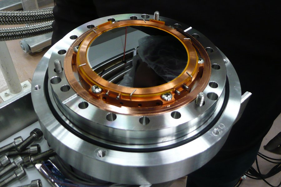
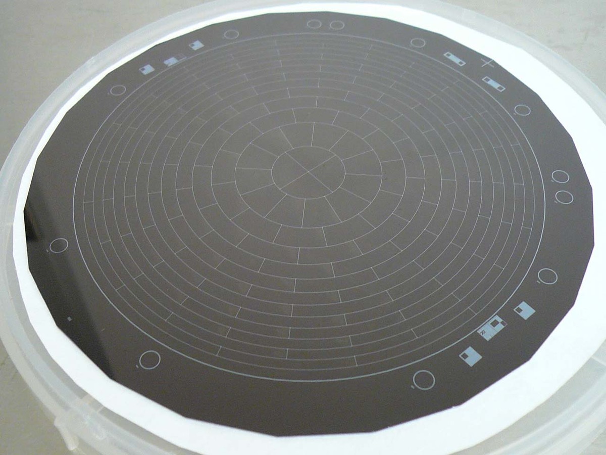
The detector is a monolithic PIN diode array on a 5"-wafer consisting of 148 pixels arranged in a “dart board” pattern which provides the spatial information. The typical energy resolution of an individual pixel is 1.4 keV (FWHM). To suppress intrinsic backgrounds, the detector is surrounded by cylinders of lead and copper shielding. Backgrounds associated with cosmic rays are tagged using a cylindrical plastic scintillator veto surrounding the lead and copper shielding. Signals from the PIN diode array and the veto are read out using custom designed electronics, ranging from the front-end preamplifiers up to the end of signal processing by the data acquisition system, including read-out software and analysis tools.
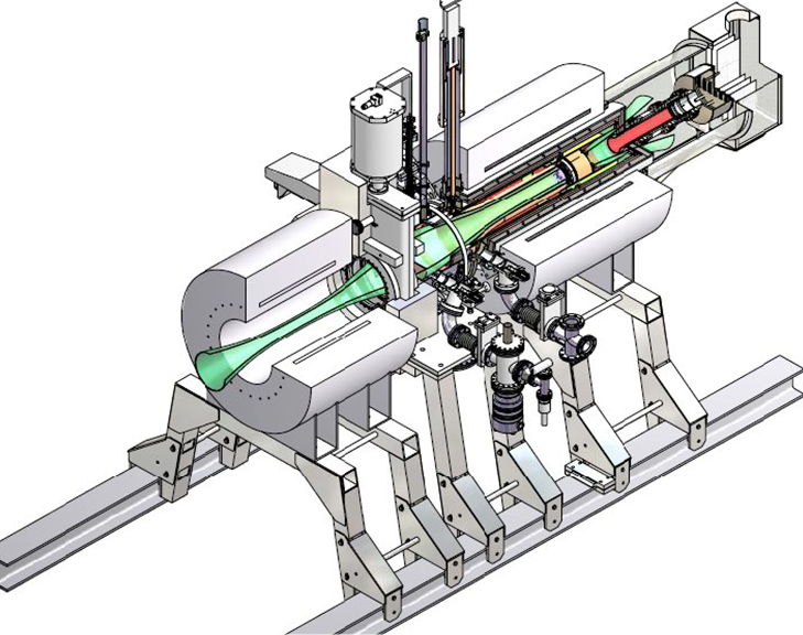
To reduce backgrounds and to be compatible with extreme ultra-high vacuum requirements, special care had to be taken in the design and manufacture of the detector. Neither of these requirements are satisfied by standard industrial mounting and connection techniques for multi-pixel silicon detectors. Compatibility with up to 6T magnetic fields and the need to mount the electronics close to the detector presents additional design challenges. The solution involved the use of a custom vacuum feedthrough with spring loaded pins contacting the individual pixels. The radioactively “hot” electronics are placed on the other side of the vacuum flange where they can be shielded by high purity copper.
As a further defense against backgrounds, the FPD system is able to provide 30 kV of “post acceleration” to the electrons coming from the main spectrometer, thereby raising them from regions of high activity to regions of low activity. Post-acceleration presents a number of challenges. The detector and its readout electronics must be read out while being biased by up to +30 kV. The application of high acceleration voltages in the presence of magnetic fields of up to 6 Tesla requires careful design in order to avoid discharges that may damage the detector and electronics.
The short summary given here can only provide a brief overview. A more in-depth discussion of the focal plane detector is given in the KATRIN design report 2004 respectively in an upcoming publication (Link to follow as soon as published). High resolution photos can be found in the Media Gallery of this homepage.
Further external links:
A status report on the commissioning and performance of the FPD - (see section Neutrino physics)
More information on the customized electronics (in german!)
More information on the readout software (link to ORCA homepage)
(29.08.2011 ms,pjd)