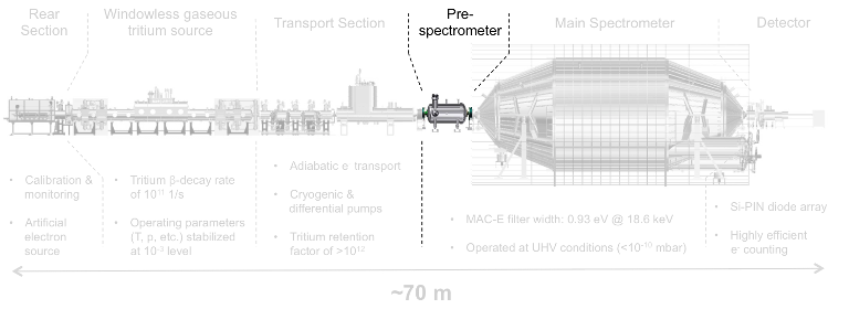
Pre-Spectrometer


The main task of the KATRIN pre-spectrometer is to limit the number of electrons which might scatter on residual gas molecules in the KATRIN main spectrometer. Both are electrostatic spectrometers operating as MAC-E filters. More details are found in our design report 2004.
The retarding field of a MAC-E-Filter is typically created by a system of cylindrical electrodes. For the KATRIN spectrometers we want to avoid a complicated inner electrode system in order to minimize the surface area in the ultra high vacuum and to simplify the construction and assembly. Therefore the retarding potential will be connected directly to the vacuum vessel. For background reduction and fine-tuning of the electric field a very simple and lightweight inner electrode system will be installed inside the vessel serving several tasks:
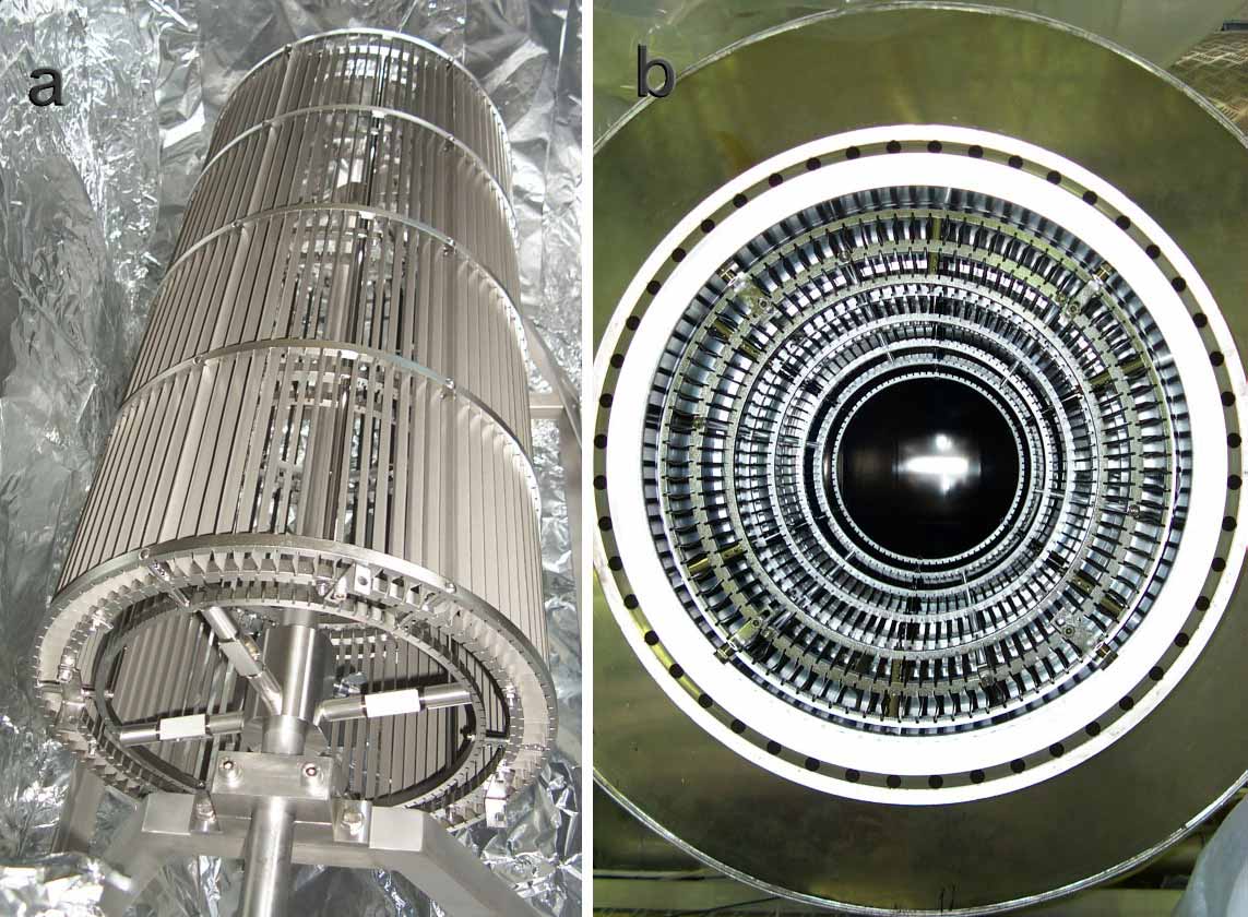
The cylindrical pre-spectrometer vessel has an outer diameter of 1.70 m, a wall thickness of 10 mm and a length of 3.38 m between the central flanges on the rounded end caps. Two large warm-bore superconducting magnets at a mutual distance of 4.30 m create a stray field of about 200 Gauss in the analyzing plane. Taking into account stray fields from all other superconducting magnets of the KATRIN setup, the magnetic field in the analyzing plane amounts to about 270 Gauss on the axis. Magnetic field lines are shown in red. The hull of the electrically insulated pre-spectrometer vessel is held at high voltage and houses an inner electrode system with a cylindrical and two conically shaped sections. The inner electrode is on a slightly more negative potential in order to reject low energy electrons from the wall (see sect. 8 of our design report). The central part of the inner electrode consists of a nearly massless wire frame. The end cones are made of sheet metal in order to avoid strong electric fields at this section where the inner electrodes are close to the ground-electrodes (green).
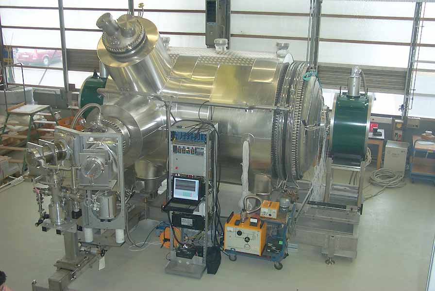
The KATRIN pre-spectrometer is a cylindrical stainless steel (316LN) vessel with rounded end caps. One of the end caps (right side in fig.2) is removable by a big flange of diameter d = 1700 mm in order to mount the inner electrodes. The electrons enter and leave the vessel through the ground electrodes within the flanges d = 500 mm in the center of both end caps, guided by the superconducting magnets at both ends. The two ports pointing sideways are for connecting the vacuum equipment: mechanical pumps, measuring devices, and they receive the getter strips needed for the required vacuum.
- Decoupling of the retarding potential from electric noise on the spectrometer vessel.
If we put the vacuum vessel on high voltage the electronic instruments and pumps connected to the vessel might be sources of electronic noise on the retarding potential. If the retarding potential is stabilized by the potential of the additional inner electrode system, noise on the hull of the vessel can be efficiently suppressed. - Electrical screening (monopole mode).
Cosmic muons and ambient or intrinsic radioactivity can induce electrons originating from the electrodes or walls. In general they should not be able to reach the detector, because the Lorentz force bends these electrons back to the
wall. However, in the Mainz II setup a small fraction of electrons created at the electrodes (≈ 10−6) still reached the detector. If the wire electrode is put at a slightly more negative potential than the tank, the bulk of these mainly low-energy electrons cannot pass this electric barrier. Experiments at Mainz have tested this idea very successfully. The wire electrodes themselves are not a significant source of electrons. - Trapped particle removal (dipole mode).
If the additional electrodes are split into two halves and put on different potentials by short pulses on one electrode, electrons passing through this region will feel a drift perpendicular to the electric dipole field E and to the magnetic field B. During these pulses the measurement would be paused. - Shaping of the electric field to avoid Penning traps.
Simulations showed the need for some shaping of the electric field to avoid Penning traps in corners. This can be achieved by either a complicated shape of the vacuum vessel or a shaping electrode system. In case of the KATRIN main spectrometer, the vacuum vessel has already an optimized shape, whereas for the cylindrical KATRIN pre-spectrometer vessel two conical ground-electrodes at the entrance and exit flanges and an inner electrode system will give the right shape to avoid the Penning traps (see fig. 3).
The very encouraging results obtained with the wire electrode system in the Mainz spectrometer (see sect. 8 of the KATRIN design report 2004) led to the design of a similar electrode system for the KATRIN pre-spectrometer.
The Pre-Spectrometer as a prototype
The pre-spectrometer has been the first major KATRIN hardware component operated at FZK. After manufacturing and initial vacuum tests at SDMS (France) the vessel was delivered to FZK in autumn 2003. Since then, a detailed experimental programme has been performed to test the KATRIN vacuum concept. The vacuum measurements have been completed at the end of 2004 when our vacuum measuring equipment specified for vacua down to 1⋅10−11 mbar went into underflow.
Since then the pre-spectrometer has been equipped with the inner electrodes, the magnets are in place, and at the two ends an e-gun and a preliminary detector are installed, respectively. This setup is starting now (autumn 2006) with the proper magnetic and electric fields to test the electromagnetic properties and our background reduction procedures.
The mechanical pumping system (turbo-molecular pumps) alone achieved about 10−8 mbar. After heating the whole vessel to a temperature of 250-300°C and cooling down again another order of magnitude was achieved. In that pressure realm the main contamination is hydrogen from the vessel walls. The final vacuum was reached by absorbing the hydrogen by strips of "getter" material which was mounted into the upper of the two pumping ports at the side of the pre-spectrometer.