Windowless Gaseous Tritium Source (WGTS)

The measurement of the neutrino mass is a high precision measurement. This requires well defined and well controlled conditions for the creation of the beta-electrons, which are analyzed for their energy in the spectrometers to reveal the secret of the neutrino mass. The Windowless Gaseous Tritium Source (WGTS) provides a required highly stable flow of beta-electrons towards the spectrometer with a technical complex and challenging control and monitoring of the Tritium gas content and composition on the 10-3 level.
In principle every radioactive beta emitting isotope could be used to look for the neutrino mass. Amongst them Tritium is a premium candidate for performing neutrino mass searches. The Karlsruhe Institute for Technology hosts with the Tritium Laboratory Karlsruhe (see fig.1) a semi-technical scale facility for processing tritium. With its license to handle up to 40 grams of tritium, its present site inventory of about 25 grams of tritium plus its extensive infrastructure and experimental apparatus TLK is the state of the art facility to perform the KATRIN experiment.
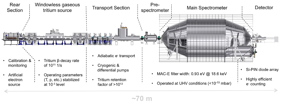
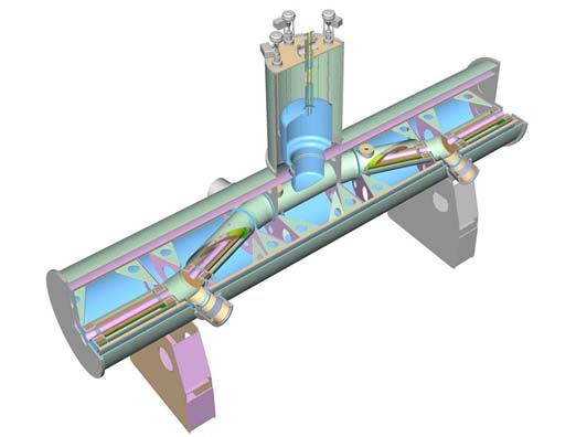
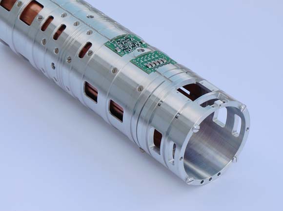
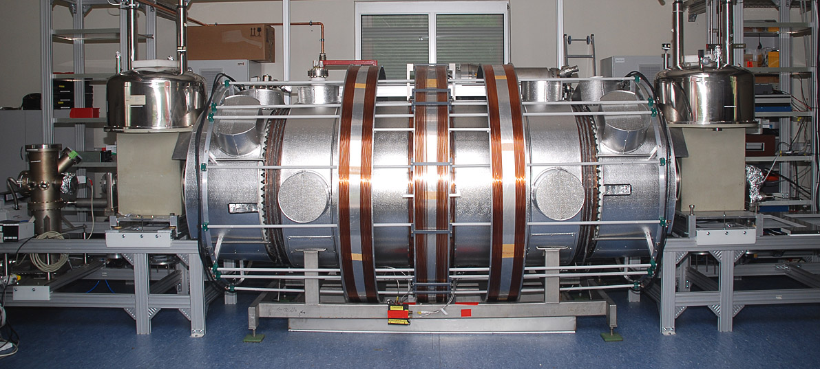
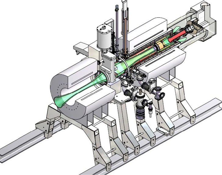
The WGTS is a tube of 10 m length and an inner diameter of 90 mm (fig 3). Cryogenic molecular tritium gas (T=27 K) of high isotopic purity (> 95%) will be injected through a set of capillaries at the middle of the 10 m long WGTS tube. The gas injection pressure pin allows adjustment of the column density ρd of the source. For a value of pin =3.4 × 10⁻³ mbar and a source tube temperature T=27 K, the column density of theWGTS is fixed to the reference value ρd= 5 × 10¹⁷ molecules/cm2. The electrons from the Tritium β-decay processes are adiabatically guided by magnetic fields of BS =3.6T to both ends of the tube. At the ends of the WGTS the molecular gas is pumped out of the system and fed back by a closed loop system, whereas the beta electrons, which are unaffected by the pumping measures , proceed their way to the spectrometers. The WGTS will deliver a total (front and rear hemispheres) of 9.5×10¹⁰ β-decays per second within the guided magnetic flux of 191 T×cm2 . (see fig 2 for WGTS schematics)
The main systematic uncertainty of the WGTS is associated with the stability of the column density ρd=5×10¹⁷ molecules/cm2 which has to be known to a precision of 0.1 %. The physical reason is that the column density, i.e. the amount of gas inside the source, determines the fraction of electrons, which escape the source with no interactions at all or energy losses due to single or double scattering with other molecules. Obviously, these energy losses have to be taken into account in the data analysis for the neutrino mass search, where on looks carefully for subtle spectral distortions of the energy spectrum. Luckily, these energy losses can be measured with special measurements. But in between the special measurements KATRIN relies on a highly stable performance of the WGTS and in situ monitoring tools. Much progress has been achieved in demonstrating stable source performance and in developments of in situ tools, in particular in the following fields:
1) Temperature stabilization
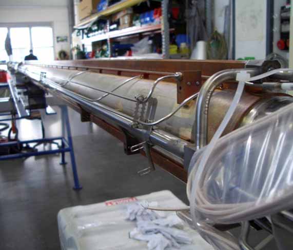
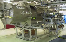
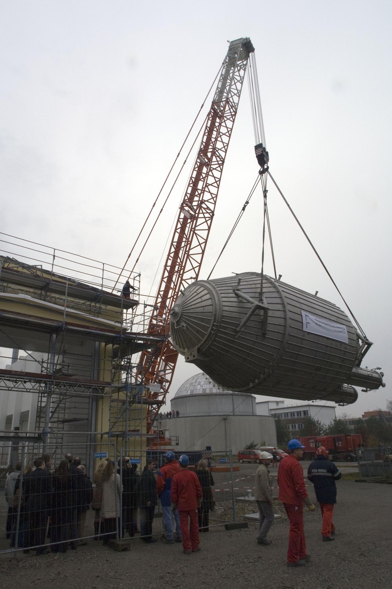
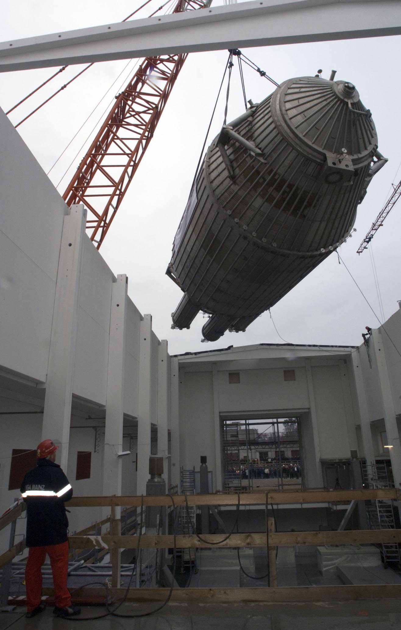
The molecular Tritium gas must be on cryogenic temperatures around 30 K in order that corrections to the electrons energy due to the thermal movement of the decaying mother atoms, do not get too large. Once having set the beam tube to a temperature in the range between 27 and 33 K, this temperature must be kept stable on the mentioned permille level. For such a large object like the 10 m long WGTS beam tube, a novel cooling concept had to be developed and tested (fig. 4) [1,2,3]. In 2011 the KATRIN collaboration was able to demonstrate with the novel cooling concept, which is based on a 2 phase liquid Neon thermosiphon, a stability as low as few mK fluctuations within hours, meeting by far the KATRIN requirements. The tests have been carried out with the so-called Demonstrator, which used the original main parts of the WGTS cryostat.
2) Pressure stabilization
As one can imagine the amount of tritium inside the source scales with the inlet pressure. It turns out that the inlet pressure must be stabilized on the same level as the temperature. This is achieved by using a large pressurized control vessel, from which the Tritium flows via a capillary to the beam tube. Already in 2009, the team working on the Tritium loop system was able to demonstrate with such a technique the required stability level for control and monitoring (fig. 5).
3) Stability of high T2 purity
KATRIN needs a high isotopic purity of molecular T2 gas (>95%). Beside T2 molecules, there are also fractions of DT and HT molecules in a gas mixture. Due to their different molecular masses and binding energies electrons from such decays have different endpoint energies. Therefore, it is crucial to keep the admixtures of such decays as small as possible. Furthermore, measuring in situ the isotopic content together with an activity measurement (see below "Monitor Detectors") allows monitoring directly the column density. With the so-called LARA system, there has been developed, commissioned and tested a ready to go Laser Raman spectroscopy system, which can measure every 200 seconds the isotopic contents of the WGTS with 0.1% precision (fig. 6) [4].
4) Monitor detectors
Particles detector, detecting directly also the low energy beta electrons from the source, have been constructed or are under tests to monitor the activity (i.e. decay rate) of the WGTS. The Forward Beam Monitor Detector is a small pin diode being positioned close to the edge of the magnetic flux tube, which is transported to the Focal Plane Detector. It can handle high data rates, while keeping the 0.1% precision, which means it takes only seconds to measure the activity of the WGTS and thus to infer together with the isotopic composition from the LARA system the column density. In addition, a x-ray detector being positioned behind the rear plate of the WGTS, will detect the induced Bremsstrahlung when the electrons hit the plate - another method to measure sufficiently precise the source activity.
Further Links:
Transport Section
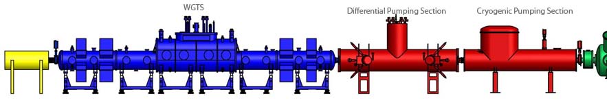
The transport section has to adiabatically guide the beta electrons from the source to the spectrometers, while at the same time eliminating any tritium flow towards the spectrometer, which has to be kept practically free of tritium for background reasons. It consists of a differential pumping section (DPS2F) and a cryogenic pumping section (CPS). In combination they must provide a tritium flow suppression by nine orders of magnitude.
The Differential Pumping Section
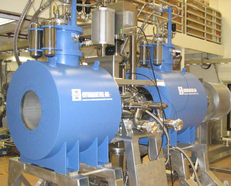
The DPS2F is a pumping section consisting of five 1 m long beam tubes within a superconducting solenoid. To block the line of sight towards the spectrometer for the diffusing, neutral tritium molecules two sections are tilted by 20 degree. Between each section there is a turbomolecular pump with a nominal pumping speed larger than 2000 l/s.
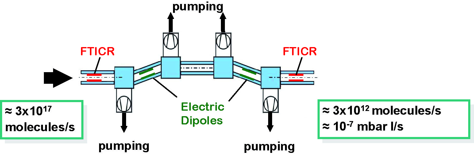
In a series of dedicated test measurements it was possible to show, that the reduction factor of the DPS amounts to 2.5x10⁴ [1]. Besides the tritium flow reduction the beam pipe of the DPS hosts instrumentation to analyze and reduce the ion flow. Ions, mostly produced by the decay of tritium into positive charged Helium, follow as charged particles or in form of positive charged molecules the magnetic fields and are blind against the pumping measures. But again, also the charged tritium is not allowed to enter the spectrometers, in order to keep background levels for the neutrino mass search sufficiently low. One trick is to bias the WGTS source and DPS by a little but known negative voltage. This prevents the positive charged ions or molecules to leave the source and DPS section. However, one has to get rid of the positive ions, as otherwise by time the source and DPS would charge significantly electrically up. To actively remove positive ions the DPS hosts with dipole electrodes and Fourier transformation Ion Cyclotron Resonators two kind of instrumentation to analyze the ion species (FTICR) and sweep them out of the beam tube (FTICR&dipoles).
Further external links
The Cryogenic Pumping Section
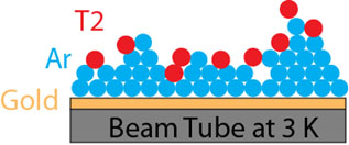
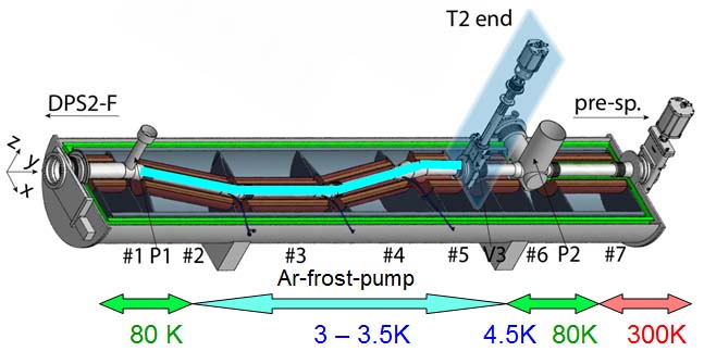
In this section all remaining traces of Tritium will be trapped by cryo-sorption onto the special prepared cold surfaces of the beam tube. For this, the gold plated beam tube will be covered at 6 Kelvin with Argon frost, which has been demonstrated to be an effcient coating for cryo-sorption of Tritium [1]. As in the case of the DPS, the beamline has a schicane to block the line of sight for the diffusing Tritium gas and to increase the probability that Tritium molecules hit the wall. The electrons are guided up to 5.6 Tesla unaffected by the cryotrap by magnetic fields towards the spectrometer. After approximately 60 days of operation the surface is saturated with Tritium and the system is warmed up to 100 K releasing the trapped Tritium. In parallel the released Tritium is removed by turbomolecular pumping with a cold valve being closed towards the spectrometers.
So at the end of the CPS, all tritium has been taken out of the beam, suppressing the partial pressure of tritium by 12 orders of magnitude compared to the inlet in the middle of he WGTS. On the other hand, the electron flow has been unaffected and has been guided adiabatically towards the spectromter. Now it is the task of the spectrometers to analyze as precisely as possible the kinetic enery of the beta electrons.
KATRIN Spectrometer Section
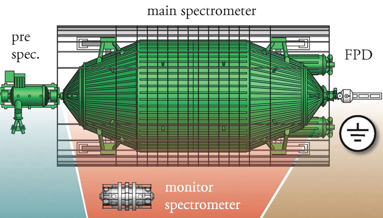
The spectrometer section includes three electro-static spectrometers (MAC-E-filter):
- The Pre-Spectrometer rejects most of the low-energy decay electrons, which carry no information on the neutrino mass.
- The Main Spectrometer measures the kinetic energy of the electrons passing the pre-spectrometer with energies close to the endpoint of the beta spectrum.
- The Monitor Spectrometer measures the position of the monoenergetic conversion electrons from 83mKr decays. It serves as a high precision "volt meter", monitoring the voltage stability of the main spectrometer.
Pre-Spectrometer


The main task of the KATRIN pre-spectrometer is to limit the number of electrons which might scatter on residual gas molecules in the KATRIN main spectrometer. Both are electrostatic spectrometers operating as MAC-E filters. More details are found in our design report 2004.
The retarding field of a MAC-E-Filter is typically created by a system of cylindrical electrodes. For the KATRIN spectrometers we want to avoid a complicated inner electrode system in order to minimize the surface area in the ultra high vacuum and to simplify the construction and assembly. Therefore the retarding potential will be connected directly to the vacuum vessel. For background reduction and fine-tuning of the electric field a very simple and lightweight inner electrode system will be installed inside the vessel serving several tasks:
The cylindrical pre-spectrometer vessel has an outer diameter of 1.70 m, a wall thickness of 10 mm and a length of 3.38 m between the central flanges on the rounded end caps. Two large warm-bore superconducting magnets at a mutual distance of 4.30 m create a stray field of about 200 Gauss in the analyzing plane. Taking into account stray fields from all other superconducting magnets of the KATRIN setup, the magnetic field in the analyzing plane amounts to about 270 Gauss on the axis. Magnetic field lines are shown in red. The hull of the electrically insulated pre-spectrometer vessel is held at high voltage and houses an inner electrode system with a cylindrical and two conically shaped sections. The inner electrode is on a slightly more negative potential in order to reject low energy electrons from the wall (see sect. 8 of our design report). The central part of the inner electrode consists of a nearly massless wire frame. The end cones are made of sheet metal in order to avoid strong electric fields at this section where the inner electrodes are close to the ground-electrodes (green).
The KATRIN pre-spectrometer is a cylindrical stainless steel (316LN) vessel with rounded end caps. One of the end caps (right side in fig.2) is removable by a big flange of diameter d = 1700 mm in order to mount the inner electrodes. The electrons enter and leave the vessel through the ground electrodes within the flanges d = 500 mm in the center of both end caps, guided by the superconducting magnets at both ends. The two ports pointing sideways are for connecting the vacuum equipment: mechanical pumps, measuring devices, and they receive the getter strips needed for the required vacuum.
- Decoupling of the retarding potential from electric noise on the spectrometer vessel.
If we put the vacuum vessel on high voltage the electronic instruments and pumps connected to the vessel might be sources of electronic noise on the retarding potential. If the retarding potential is stabilized by the potential of the additional inner electrode system, noise on the hull of the vessel can be efficiently suppressed. - Electrical screening (monopole mode).
Cosmic muons and ambient or intrinsic radioactivity can induce electrons originating from the electrodes or walls. In general they should not be able to reach the detector, because the Lorentz force bends these electrons back to the
wall. However, in the Mainz II setup a small fraction of electrons created at the electrodes (≈ 10−6) still reached the detector. If the wire electrode is put at a slightly more negative potential than the tank, the bulk of these mainly low-energy electrons cannot pass this electric barrier. Experiments at Mainz have tested this idea very successfully. The wire electrodes themselves are not a significant source of electrons. - Trapped particle removal (dipole mode).
If the additional electrodes are split into two halves and put on different potentials by short pulses on one electrode, electrons passing through this region will feel a drift perpendicular to the electric dipole field E and to the magnetic field B. During these pulses the measurement would be paused. - Shaping of the electric field to avoid Penning traps.
Simulations showed the need for some shaping of the electric field to avoid Penning traps in corners. This can be achieved by either a complicated shape of the vacuum vessel or a shaping electrode system. In case of the KATRIN main spectrometer, the vacuum vessel has already an optimized shape, whereas for the cylindrical KATRIN pre-spectrometer vessel two conical ground-electrodes at the entrance and exit flanges and an inner electrode system will give the right shape to avoid the Penning traps (see fig. 3).
The very encouraging results obtained with the wire electrode system in the Mainz spectrometer (see sect. 8 of the KATRIN design report 2004) led to the design of a similar electrode system for the KATRIN pre-spectrometer.
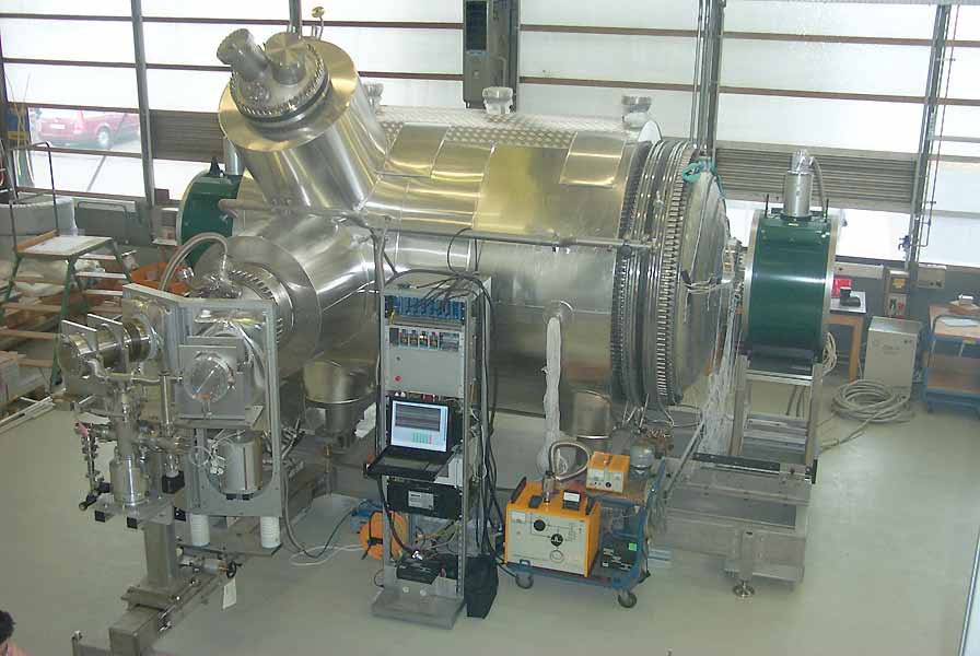
The Pre-Spectrometer as a prototype
The pre-spectrometer has been the first major KATRIN hardware component operated at FZK. After manufacturing and initial vacuum tests at SDMS (France) the vessel was delivered to FZK in autumn 2003. Since then, a detailed experimental programme has been performed to test the KATRIN vacuum concept. The vacuum measurements have been completed at the end of 2004 when our vacuum measuring equipment specified for vacua down to 1⋅10−11 mbar went into underflow.
Since then the pre-spectrometer has been equipped with the inner electrodes, the magnets are in place, and at the two ends an e-gun and a preliminary detector are installed, respectively. This setup is starting now (autumn 2006) with the proper magnetic and electric fields to test the electromagnetic properties and our background reduction procedures.
The mechanical pumping system (turbo-molecular pumps) alone achieved about 10−8 mbar. After heating the whole vessel to a temperature of 250-300°C and cooling down again another order of magnitude was achieved. In that pressure realm the main contamination is hydrogen from the vessel walls. The final vacuum was reached by absorbing the hydrogen by strips of "getter" material which was mounted into the upper of the two pumping ports at the side of the pre-spectrometer.
Main Spectrometer
The main spectrometer has to analyze the endpoint region of the tritium β spectrum with an unprcedented precision.. All electromagnetic properties have to be known very precisely and kept under strict control. Like the pre-spectrometer it operates as an electrostatic spectrometer in the MAC-E filter mode. More details are given in our design report 2004.
The combination of a large recipient and stringent ultra high vacuum (XHV) requirements presents a technological challenge, since XHV vessels of this size have never been built before!
The main vessel is manufactured from stainless steel sheets, type 1.4429 (316LN), selected both for its strength and excellent magnetic properties especially in weld regions. The weight is approximately 200 tons. There are limits on the amount of cobalt permitted in the steel and on its residual radioactivity to minimize background in the spectrometer. The thickness varies from about 25 to 32 mm.
Three pump ports, each of 1.7 m diameter, are attached at the downstream end. A piping system for heat transmission by thermal oil is realised by soldering U-shaped stainless steel profiles to the surface. The tank stands provide an electrical insulation (marked yellow in fig.1).
The properties of the vessel are:
- inner diameter of the cylindrical section: 9.8m, total length: 23.28m
- inner surface: 650m2, volume: 1400m3
- three pump ports with a diameter of 1.7m and a length of ≈ 3 m. Each pump port will terminate in a large flange, similar to the one tested in the pre-spectrometer.
- the electron beam will enter the spectrometer through a ground electrode attached to a ceramic insulator on a 500mm flange, similar to the design used for the pre-spectrometer.
- during bake-out at 350°C the vessel will expand by 20 cm along the axis. In order to prevent damage to the upstream sections, it will be fixed to the floor at its upstream end. The downstream end will push back the transport section and the detector. Therefore all downstream installations have to be mounted on rails. The vessel has been ordered in December 2004 and was delivered to FZK in November 2006.
The electrode design is based on the concept that the vacuum tank itself serves as a guard electrode for the more accurate high voltage on the inner wire electrode system. The electron beam enters and leaves the vessel through conical ground electrodes attached to the spectrometer via ceramic insulators. The actual design of the inner electrode system and of the ground electrodes has been optimized further compared to fig. 2. Stringent requirements on the homogeneity of the electric retarding potential and the magnetic field in the analyzing plane are necessary to reach the ambitious energy resolution of 0.93 eV and to suppress systematic errors.
Small inhomogeneities of the electric retarding potential and of the magnetic field in the analyzing plane will be compensated to first order by the good spatial resolution of the detector. The electron flux through the analyzing plane will be projected on a segmented electron detector, which has a resolution of about 400 pixels (20 × 20). Each pixel corresponds to a certain area on the analyzing plane. The inhomogeneities of the electric potential and of the magnetic fields have been calculated and can be used to correct deviations for each pixel.
The inner electrode system will suppress electrons from the spectrometer wall. It can be also operated in dipole mode, throwing out trapped electrons: If the electrodes are split into two halves (left and right sides) and put on different potentials by short pulses of up to 1 kV on one electrode, electrons passing through this region will feel a drift perpendicular to the electric dipole field E and to the magnetic field B. During these pulses the measurement would be paused.
The inner electrode system will consist of about 200 wire modules with a weight of 20–30 kg each. These modules will be brought into the spectrometer through one of the large diameter flanges (pump ports) and mounted via electrical insulators onto the walls. An ultra-high precision high voltage system will feed the different wire layers and wire sections as well as the outer vessel with the necessary voltages for the normal monopole and the dipole mode. High precision variation of the main spectrometer potentials will be possible for scanning the β spectrum near its endpoint.
Status of the Main Spectrometer
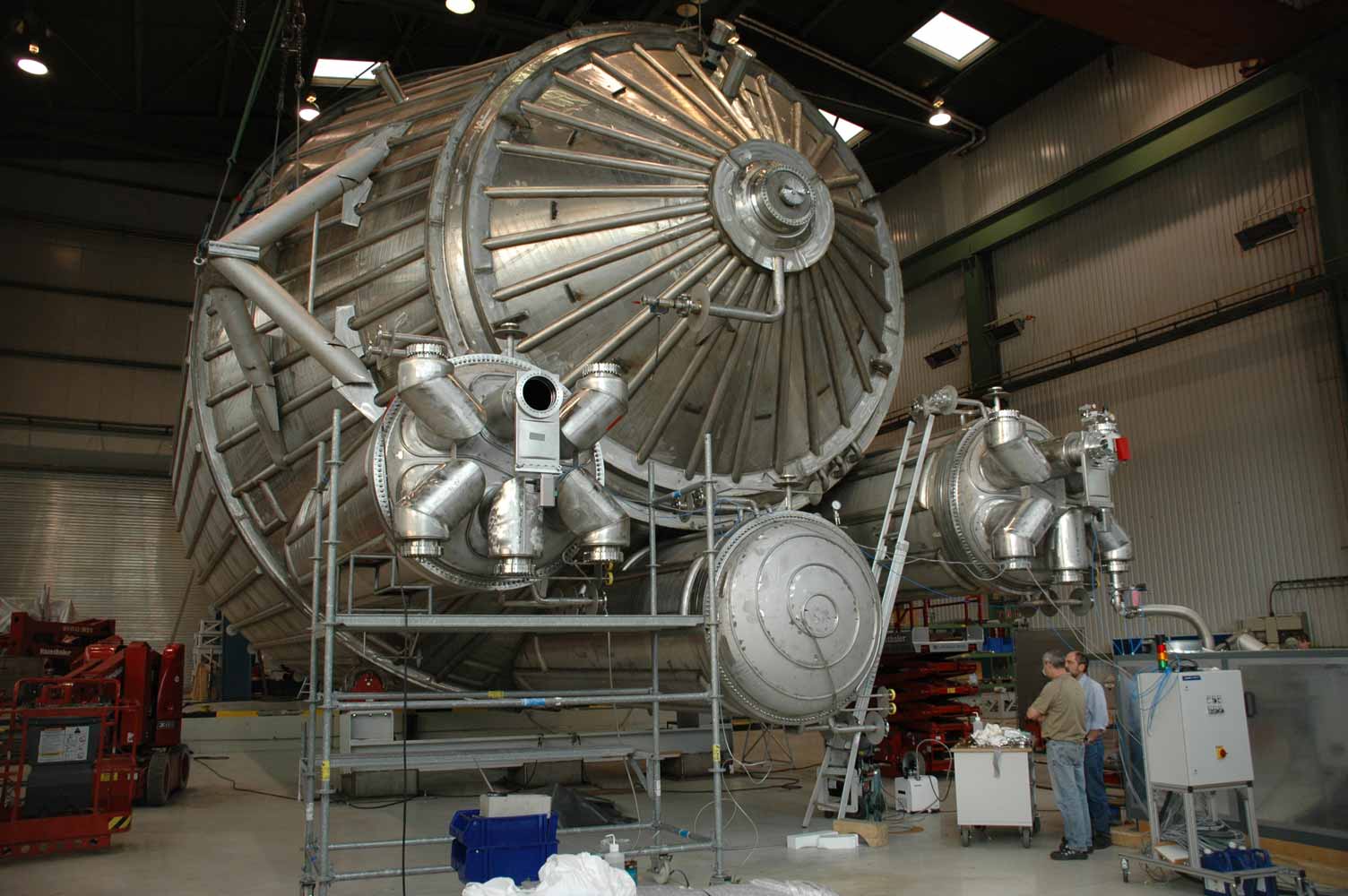
The main spectrometer has been manufactured by MAN DWE at the Deggendorf plant adjacent to the river Danube (Donau). Fig. 4 shows the downstream end of the vessel with the three pumping ports. Only two ports will actually be equipped with mechanical pumps.
Vacuum tests started a few days after the picture above was taken. Only one pumpiing system (fore-pump and turbomolecular pump) was used. The instrument which measured the vacuum was in the pumping port which was not used for pumping. After pumping for two days with the fore-pump alone, a vacuum of 1.5×10⁻³ mbar was achieved. Switching on the turbo gave 2×10⁻⁵ mbar after one hour, going down to 3×10⁻⁷ mbar after a few days. Then another turbo was put between the two pumps in order to reduce the pressure ratio between pump entrance and exit.. This brought the pressure down to 8×10⁻⁸ mbar after a short time. This is an excellent value, especially for the first try with a newly built vessel of this size, and demonstrates a proper design, quality control, and good craftsmanship during the manufacturing of the vessel!
Our goal is to achieve a vacuum at least four orders of magnitude better than the value reached now. Therefore a test to find tiny leaks with a helium leak test device followed the vacuum tests. No leaks were found, and after that we can be confident that we will reach the required vacuum by temporarily baking the tank under vacuum up to 350°C to force the gas out of the walls, using four instead of one pumping systems, and by the getter strips (see pre-spectrometer) which are activated by heating and are highly efficient to remove hydrogen which is the main component of outgassing from steel at XHV conditions.
After the leak tests the tank was ready to be shipped. There is a slight problem of transportability from Deggendorf to Karlsruhe: The tank is too big for motorways, and the canal between the rivers Rhine and Danube has to be ruled out, too. Thus, instead of a journey of about 400 km, the spectrometer has to travel nearly 9000 km as indicated in the map.
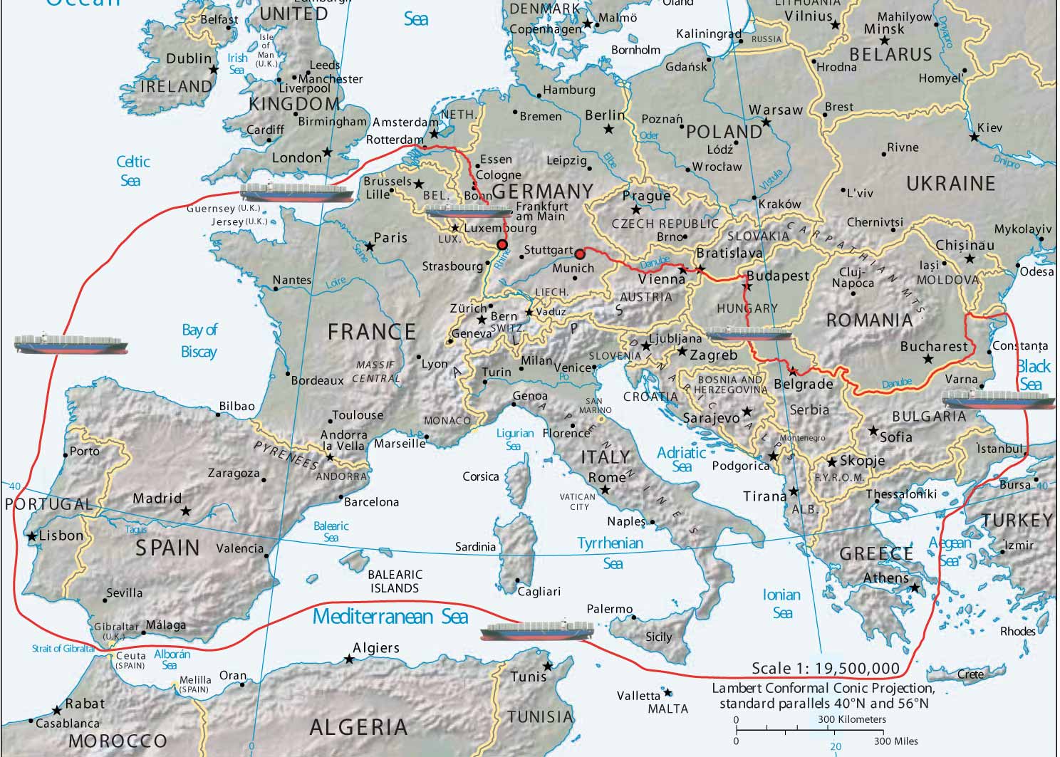
*) Map courtesy of the University of Texas Libraries, The University of Texas at Austin.
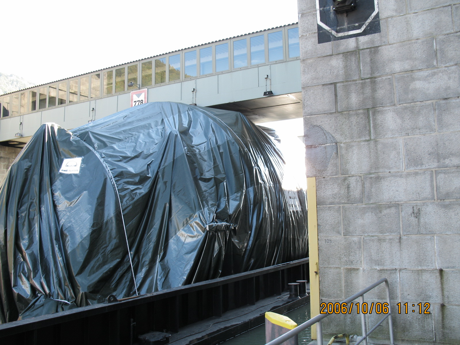
Fig. 6: Passing Jochenstein lock
September 28, 2006: The main spectrometer was loaded onto the river barge "Taifun" (i.e. "typhoon"!). Eight days later, after picking up ~1400 to of gravel and 800 to of water as ballast, the vessel managed to pass the bridge at Jochenstein lock (left) with a luxury safety margin of 7cm (!) on top and continued its journey safely in Austria. The next critical point was Wildungsmauer between Vienna and Bratislava where some ballast had to be unloaded to manage the water depth.
The Danube delta was reached mid October. At the port of Constanta the main spectrometer vessel was transferred to the sea-going ship ANNEGRET which left port on October 31, 2006.
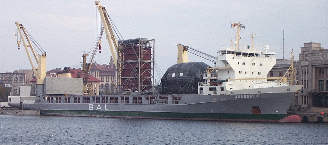
Fig. 7: Main spectrometer vessel aboard the ANNEGRET at Constanta
After a rough ride through the Black Sea aboard the ANNEGRET the spectrometer vessel passed the Bosporus and reached the port of Augusta / Sicily on Nov 6. The storm blew away the protective cover so the spectrometer can now be seen in all its glory, meaning that a bit of cleaning will have to be done! At Augusta the spectrometer was transferred to the SVENJA to carry it to the estuary of the Rhine.
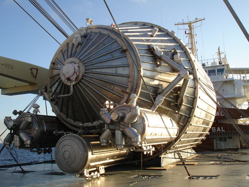
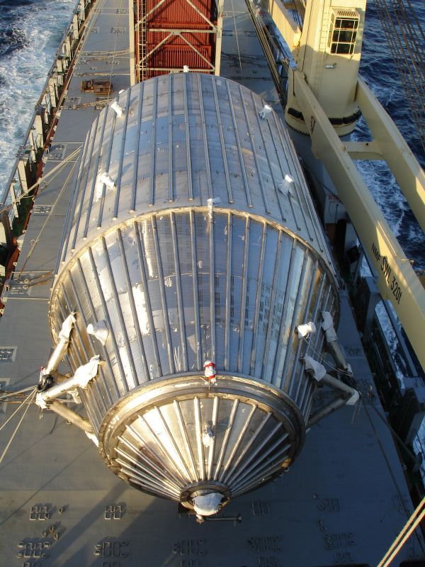
Fig. 8: The "naked" spectrometer aboard the ANNEGRET, left: Pump ports, right: upstream end
After a short detour to the port of Civitavecchia near Rome, the SVENJA went due west to pass the straits of Gibraltar on November 13, then turned north to reach the estuary of the river Rhine on November 17.
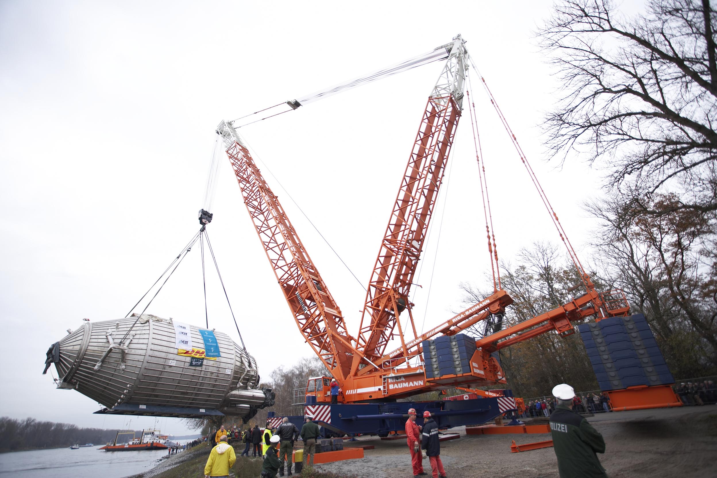
Due to low water levels on the
| Nov 23 (Th) | Assembling of a heavy lifting crane started at Leopoldshafen (at the "NATO ramp"). | |
| Nov 24 (Fr) | The main spectrometer vessel arrived at Leopoldshafen. | |
| Nov 25 (Sa) | morning | The spectrometer vessel was loaded onto a carrier vehicle by the heavy lifting crane. |
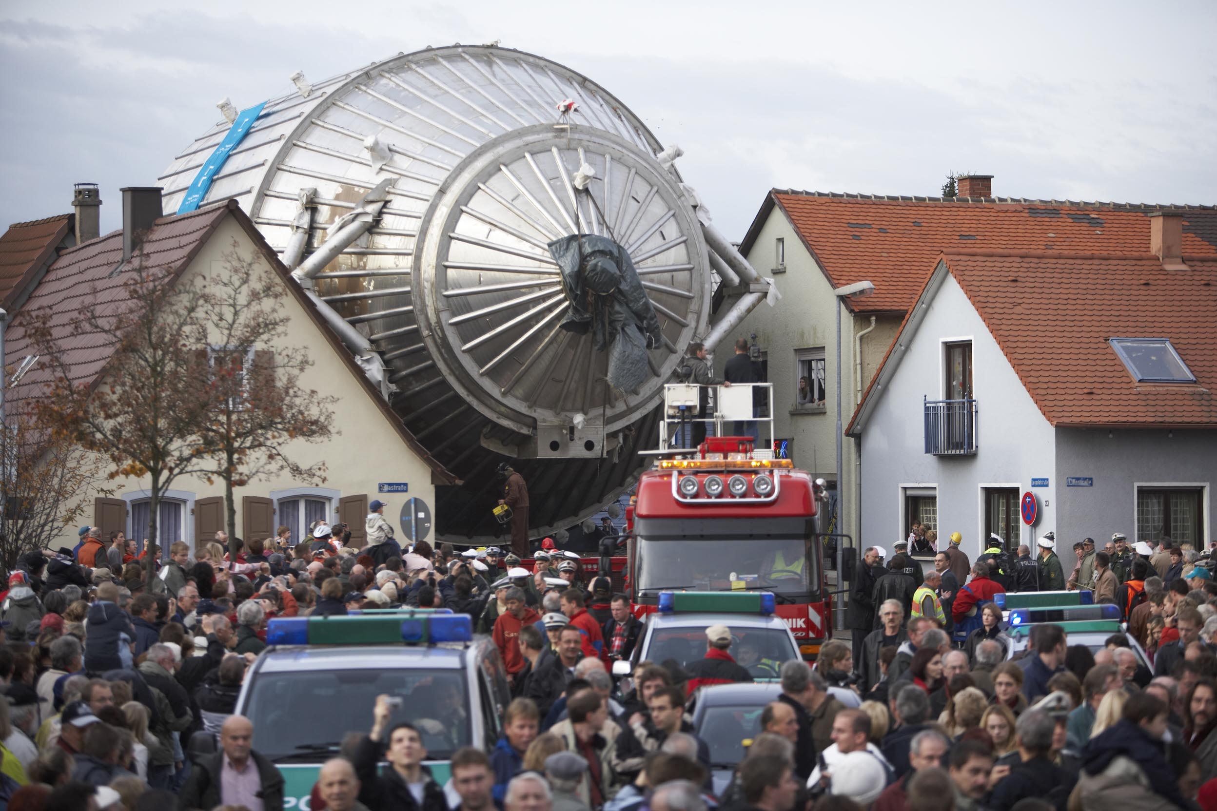
| daytime | The vessel was transported to FZK through the village of Leopoldshafen. | |
| afternoon | Arrival at FZK | |
| Nov 25-28 | Disassembling of the crane and reassembling at FZK | |
| Nov 29 (We) | The spectrometer was lifted over the side walls of its new hall into the final position. |
The main spectrometer has now safely reached its destination!
Monitor Spectrometer
The monitor spectrometer is used to monitor the stability of the high voltage of the main spectrometer. Like the main spectrometer, it is operated as a MAC-E-Filter. It measures the energy of conversion electrons from the Krypton-83m decay, which have always the same energy. Basically it is an almost 10m long, very accurate voltmeter, using a nuclear standard as a reference.
Detector
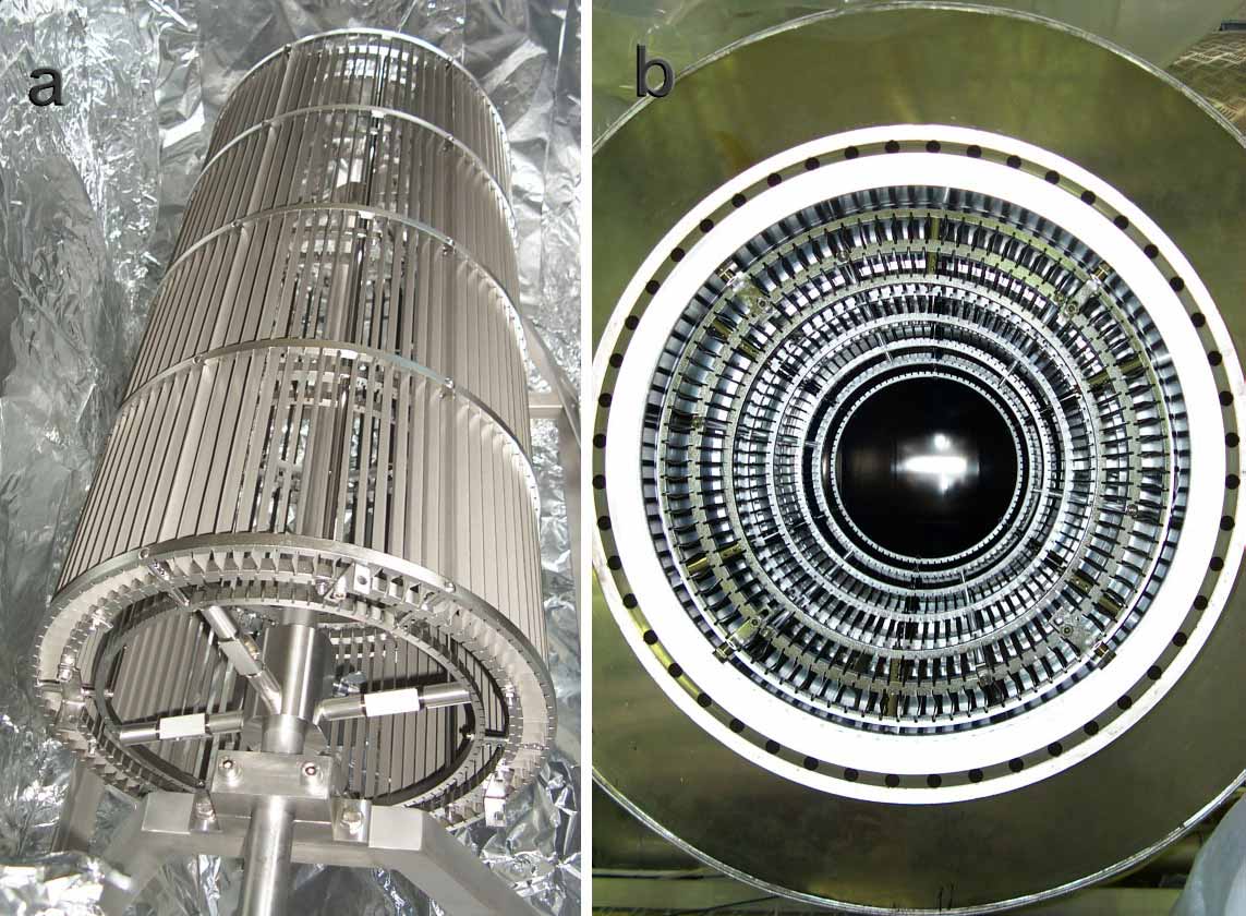
After passing the retarding potential of the main spectrometer all β-electrons are re-accelerated to their initial energy and magnetically guided to the focal plane detector (FPD). The FPD is located inside the second magnet of a pair of superconducting magnets. To lower the detector background rate, the large diameter, warm bore, of this solenoid magnet is wide enough to accommodate active and passive detector shielding. The detector is a multi-pixel silicon semiconductor detector with high energy resolution and thin entrance window.
In principle KATRIN would only require a simple electron counter to determine how many electrons have crossed the retarding potential. In practice, energy, spatial, and temporal information is very important in both understanding the operation of the apparatus and sources of background. The two main reasons we need more information than just counting of the electrons are:
- The electric potentials e.g. at the source and at the analyzing plane of the main spectrometer vary slightly, depending on the radial position. These distortions can be calculated or measured. The position of the electrons as it passes the analyzing plane is imaged in the position at which it strikes the detector. A position-sensitive detector allows the varying electric potentials to be mapped and to apply corrections to each detected electron.
- There are various sources of background, mainly electrons produced by ionization in the residual gas, electrons from interactions of cosmic rays, and γ-rays from natural radioactivity emanating from material surrounding the detector and from the detector itself. Here, positional information also helps, but most important is the accurate determination of the electron's energy. β-electrons of interest occur in a narrow energy window, whereas backgrounds vary over a large range of energies, thus, accurate energy determination improves the ability to separate β-electrons for backgrounds.
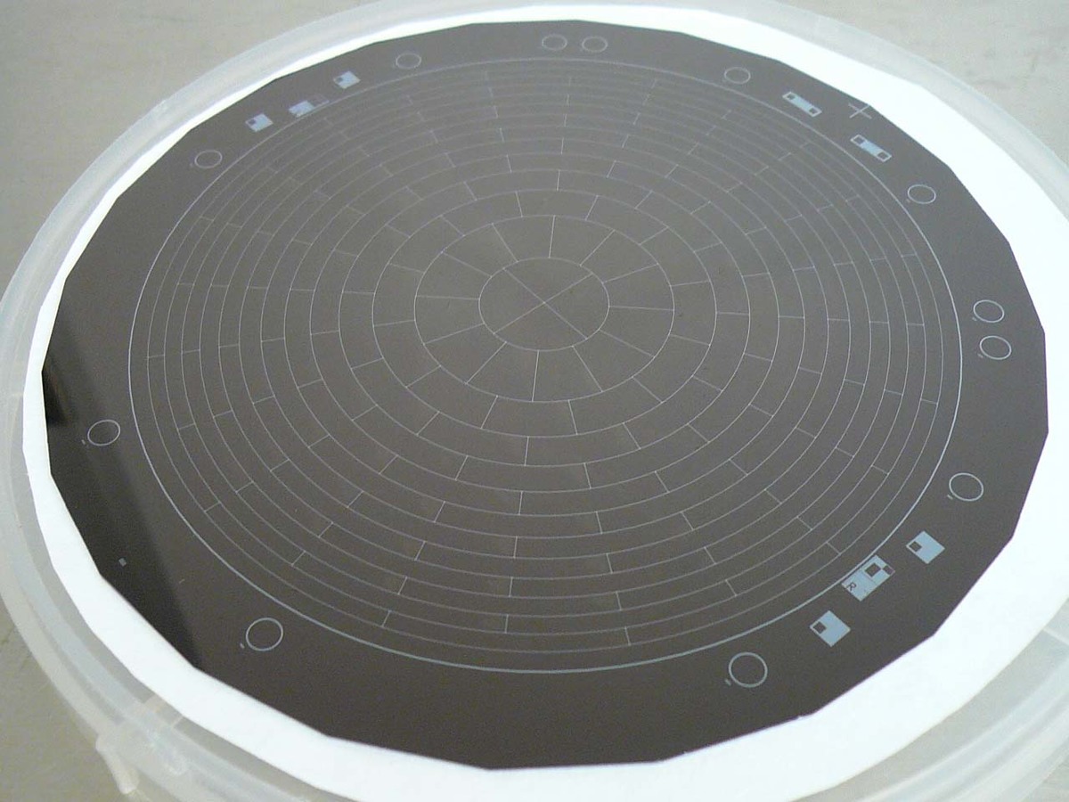
The detector is a monolithic PIN diode array on a 5"-wafer consisting of 148 pixels arranged in a “dart board” pattern which provides the spatial information. The typical energy resolution of an individual pixel is 1.4 keV (FWHM). To suppress intrinsic backgrounds, the detector is surrounded by cylinders of lead and copper shielding. Backgrounds associated with cosmic rays are tagged using a cylindrical plastic scintillator veto surrounding the lead and copper shielding. Signals from the PIN diode array and the veto are read out using custom designed electronics, ranging from the front-end preamplifiers up to the end of signal processing by the data acquisition system, including read-out software and analysis tools.
To reduce backgrounds and to be compatible with extreme ultra-high vacuum requirements, special care had to be taken in the design and manufacture of the detector. Neither of these requirements are satisfied by standard industrial mounting and connection techniques for multi-pixel silicon detectors. Compatibility with up to 6T magnetic fields and the need to mount the electronics close to the detector presents additional design challenges. The solution involved the use of a custom vacuum feedthrough with spring loaded pins contacting the individual pixels. The radioactively “hot” electronics are placed on the other side of the vacuum flange where they can be shielded by high purity copper.
As a further defense against backgrounds, the FPD system is able to provide 30 kV of “post acceleration” to the electrons coming from the main spectrometer, thereby raising them from regions of high activity to regions of low activity. Post-acceleration presents a number of challenges. The detector and its readout electronics must be read out while being biased by up to +30 kV. The application of high acceleration voltages in the presence of magnetic fields of up to 6 Tesla requires careful design in order to avoid discharges that may damage the detector and electronics.
The short summary given here can only provide a brief overview. A more in-depth discussion of the focal plane detector is given in the KATRIN design report 2004 respectively in an upcoming publication (Link to follow as soon as published). High resolution photos can be found in the Media Gallery of this homepage.
Further external links:
A status report on the commissioning and performance of the FPD - (see section Neutrino physics)
More information on the customized electronics (in german!)
More information on the readout software (link to ORCA homepage)
(29.08.2011 ms,pjd)